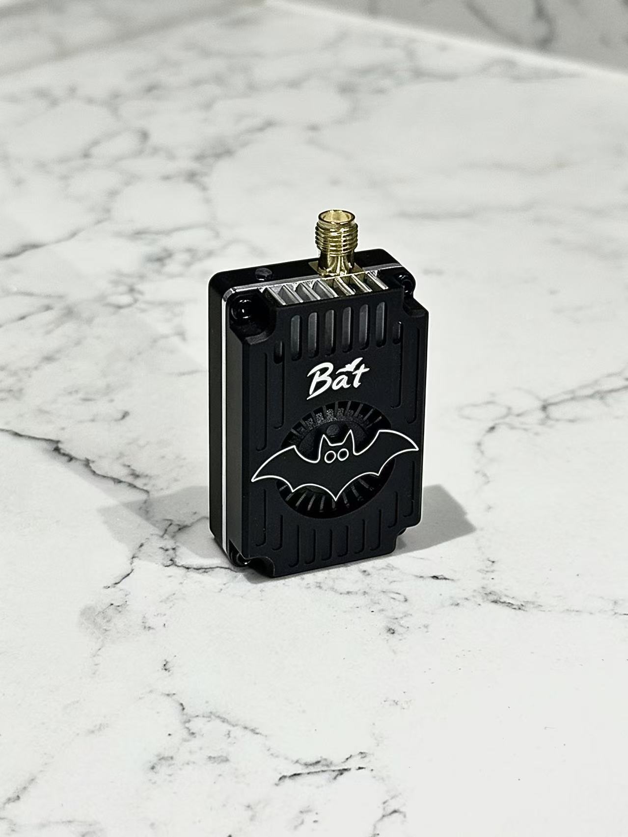
Description
Features
-Customized wide bandwidth and high-power amplifier are used to achieve full output within the entire working bandwidth.
-The modulation circuit uses industrial microchips and is digitally closed-loop controlled. It can operate stably in harsh environments.
-All X-SPAN series products have undergone rigorous quality inspection procedures, including full-channel power calibration and aging tests.
-The sturdy aluminum alloy casing is cooled by an active fan.
-It incorporates a high-gain broadband antenna and is system-matched to achieve the optimal transmission efficiency.
Specification
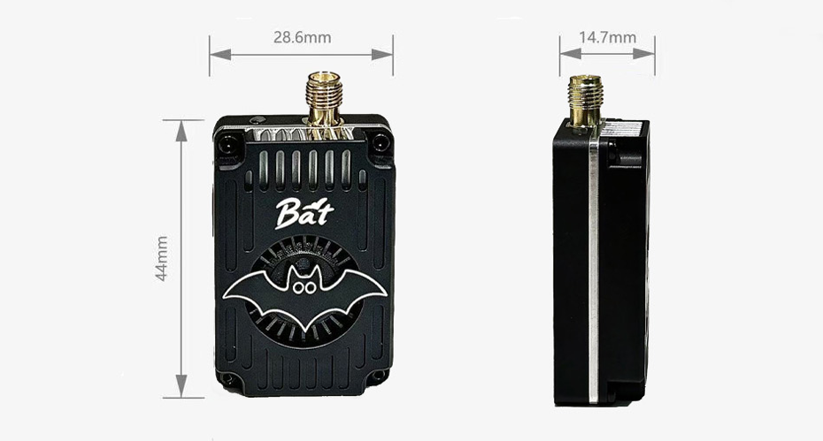
3.1GHz-3.8GHz VTX 5W
| Frequency band | 3170-3790MHz |
|---|---|
| Channel customer | 32CH |
| Modulation type | FM |
| RF Power | PIT-25mW-200mW-1W-5W |
| Power Supply | DC 7-30V |
| Operating Temperature | -10℃~+70℃ |
| Control Protocol | IRC Tramp |
| Dimension | L44XW28.6XH14.7mm |
| Weight | 25.6g |
3.2GHz-4.1GHz ANTENNA
| Polarization | Linear |
|---|---|
| Bandwidth | 3200MHz-4100MHz |
| Radiation pattern | Omni-directional |
| Gain | ≤4.6dBi |
| V.S.W.R | ≤1.5 |
| Cable | RG402 |
| Connector | SMA Male |
| Impedance | 50 Ohm Nominal |
| Dimension | H163 X W43mm |
| Weight | 11g |
Frequency Table
| CH1 | CH2 | CH3 | CH4 | CH5 | CH6 | CH7 | CH8 | ||
|---|---|---|---|---|---|---|---|---|---|
| 1 | BAND A | 3330 | 3350 | 3370 | 3390 | 3410 | 3430 | 3450 | 3470 |
| 2 | BAND B | 3170 | 3190 | 3210 | 3230 | 3250 | 3270 | 3290 | 3310 |
| 3 | BAND E | 3490 | 3510 | 3530 | 3550 | 3570 | 3590 | 3610 | 3630 |
| 4 | BAND F | 3650 | 3670 | 3690 | 3710 | 3730 | 3750 | 3770 | 3790 |
Power Levels
| Values | P0 | P1 | P2 | P3 | P4 |
|---|---|---|---|---|---|
| Power Level | PIT | 25mW | 200mW | 1w | 5W |
| Typ. | -40dBm | 14dBm | 23dBm | 30dBm | 37dBm |
Wiring and Operation
Properly install the antenna before use!
-
The included antenna is fully matched to the VTX's operating frequency band and requires no trimming. If using a different antenna, ensure its operating frequency matches the VTX!
-
Improper operation may impair VTX performance or cause damage to the VTX!
-
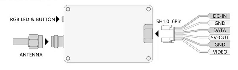
Controlled using a single button, the button integrates RGB lighting, blue for band, red for channel, and green for power level.
-
When there is no operation, the RGB LED blinks cyclically, the number of times the RGB blinks represents the current VTX status (when the green LED is always on, the VTX enters PITMODE).
-
Long press the button to enter VTX setting, at this time the RGB lights are lit alternately, release the button under the corresponding color light to enter the corresponding function setting. At this time, short press the button to adjust the value.
-
For setup via the flight controller, connect the DATA pin and use the IRC Tramp protocol.
Reviews
There are no reviews yet.