
Description
Advantages of the primary and secondary combustion chamber combined vertical incinerator:
1: Incineration of gas and liquid at the same time,
2: Simple equipment structure, small heat loss of the main body,
3: Low floor space requirement,
4: Equipment procurement cost.
The furnace volume of the combined incinerator is based on the exhaust gas generated by incineration, the comprehensive residence time is ≥4s, the high-temperature (1100℃) incineration treatment is ≥1100℃, and the high-temperature section residence time is ≥2.5s to ensure the removal efficiency of organic matter.
Equipment description:
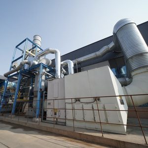
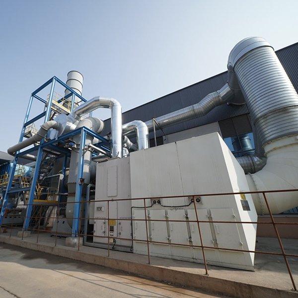
Primary and secondary combustion chamber combined vertical incinerator:
Material parameters to be processed (provided by the owner)
The shell of the incinerator is made of steel plate, and the inner lining is made of wear-resistant and corrosion-resistant corundum refractory materials, which can work reliably for a long time at high temperature. The steel plate and the refractory material are lined with thermal insulation materials to prevent heat from being easily transferred out. The combustible gas and particles contained in the flue gas are further burned with the help of the burner flame and multiple winds, so that the temperature of the combustion chamber is maintained above 1100℃, ensuring that the harmful substances contained in the flue gas are fully burned. The primary combustion chamber and the secondary combustion chamber of this project are integrated in a vertical furnace, with the first combustion chamber at the bottom and the second combustion chamber at the top. The combustion-supporting, oxygen-supplementing, temperature control, and detection systems are independent systems separated from each other and do not interfere with each other.
The characteristics of this incinerator are summarized as follows:
(1) This equipment can burn both liquid and gas at the same time, and has strong adaptability to the incineration materials;
(2) The heat utilization rate is relatively high;
(3) The temperature in the incinerator can reach 850-1100℃, which can basically burn out the hazardous waste; the strong gas mixing in the secondary combustion chamber makes the unburned materials in the flue gas completely burn to the high temperature (1200℃) required for the decomposition of harmful components, and the flue gas residence time in the high temperature zone is greater than 2.5 seconds; not only can the waste be burned thoroughly, but also the working condition area where dioxins are produced is avoided or reduced from the source;
(4) Good sealing measures and negative pressure in the furnace ensure that harmful gases do not leak out;
(5) The equipment has a high operating rate, and the annual operating rate can generally reach 90%; it is easy to operate and maintain;
Incineration overview
Incineration is a high-temperature pyrolysis treatment technology. That is, a certain amount of excess air and the treated organic waste are subjected to oxidation combustion reaction in the incinerator, and the harmful and toxic substances in the waste are oxidized and pyrolyzed at a high temperature of 1100°C and destroyed. It is a treatment technology that can simultaneously achieve the harmlessness, reduction and resource utilization of waste.
The purpose of incineration is to burn the waste as much as possible, make the incinerated substances harmless and minimize the volume, and minimize the generation of new pollutants to avoid secondary pollution. For the incineration of waste, it can simultaneously achieve the three goals of reducing the amount of waste, completely burning the toxic substances in the waste, and recycling the waste heat generated by incineration.
Incineration is a thermal technology for treating waste by burning. There are three main components in the combustion system: fuel or combustible material, oxide and inert material. Fuel is an organic substance containing high-energy chemical bonds such as carbon, carbon-hydrogen and hydrogen. These chemical bonds will release heat energy after oxidation; oxides are indispensable substances in the combustion reaction. The most common oxide is air containing 21% oxygen. The amount of air and the degree of mixing with the fuel directly affect the efficiency of combustion; inert substances do not directly participate in the combustion process. The combustion process of combustible substances is relatively complex, usually consisting of heat and mass transfer processes such as thermal decomposition, melting, evaporation and chemical reaction.
Process flow chart

Brief description of the main process flow
1) First, turn on the blower to purge the residual gas and other flammable and explosive gases in the furnace to prevent explosion after ignition.
2) Before the ignition burner is ignited, turn on the induced draft fan and purge the furnace for five minutes. The combustion-supporting fuel natural gas is transported through the pipeline and ignited by the ignition burner. The burner releases heat to slowly increase the temperature in the first and second combustion chamber sections to 1100℃.
3) The waste liquid enters the waste liquid furnace through the waste liquid pipeline through the atomizing spray gun. The outlet temperature of the first combustion chamber section can be controlled by controlling the amount of waste liquid.
4) When the combustion temperature of the secondary combustion chamber is above 1100°C, the exhaust gas is sent into the furnace through a dedicated exhaust gas burner. The high-temperature flue gas in the furnace fully oxidizes the organic matter in the exhaust gas.
5) The flue gas generated in the first combustion chamber section enters the second combustion chamber section, and the ash generated by incineration falls to the bottom and is automatically discharged by the scraper.
6) The high-temperature flue gas is further burned in the secondary combustion chamber. The combustion temperature is controlled at 1100℃ to make the combustion more complete and achieve the effect of smokeless, odorless and no secondary pollution. The secondary residence time of flue gas is more than 2.5 seconds, so that trace organic matter and dioxins in the flue gas can be fully decomposed. The decomposition efficiency exceeds 99.99%, ensuring that undecomposed organic components and carbon particles in the flue gas are completely decomposed at a temperature of about 1100°C. Multi-stage combustion is used in the secondary combustion chamber, which effectively suppresses the generation of nitrogen oxides.
7) The flue gas from the secondary combustion chamber enters the waste heat steam boiler. Spray 8% ammonia solution (can replace 16% urea solution) at the boiler inlet to perform high-temperature SNCR reduction and denitrification to remove NOx in the flue gas. Then the high-temperature flue gas exchanges heat with the boiler evaporation tube bundle, and the saturated steam is produced and enters the factory pipe network. At the same time, the ash in the flue gas is further settled in the boiler cavity, improving the cleanliness of the flue gas.
8) The flue gas from the boiler enters the semi-dry quenching tower. The spray reflux liquid is transported by a pressurized pump and sent into the reaction tower through the two-fluid nozzle at the top of the reaction tower. It is atomized into fine droplets through a two-fluid nozzle. The atomized droplets are affected by the upward hot smoke, forming a high-density area near the nozzle where the droplets are suspended. By adjusting the injection volume, the temperature is controlled to quickly drop to about 200°C within 1 second, thereby effectively inhibiting the regeneration of dioxin. At the same time, some sparks in the smoke are extinguished by the sprayed water mist, protecting subsequent bags from being burned.
9) Then the flue gas enters the dry acid removal and dioxin absorption device, which is equipped with a storage tank for lime and activated carbon. The lime and activated carbon are transported by the ash discharge valve and purged by high-pressure air, and then enter the connecting flue to react with the incineration exhaust gas. Purify exhaust gas. The function of spraying carbon lime is to remove acidic components such as HCl and NOx in the absorbed flue gas. The function of activated carbon is to adsorb and remove small amounts of dioxins, furans, etc. remaining in the flue gas.
10) The exhaust gas enters the air box bag dust collector to remove the fine dust retained in the flue gas. The mixture of carbon lime and activated carbon sprayed in the dry spray tower enters the bag dust collector and is adsorbed on the bag. The carbon lime and activated carbon that are not fully reacted and adsorbed continue to absorb and react.
11) What comes out of the bag enters the precooling tower, the second-stage lye washing tower, and the water washing tower for four times of cooling and washing. The main function is to wash away acid gas and dust in the flue gas. After reaching the standard, the flue gas passes through the chimney through the induced draft fan to achieve the standard emission.
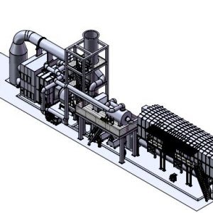
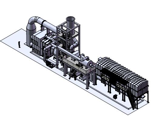
Main process
Automatic feeding system – vertical combined combustion chamber – SNCR denitrification system – waste heat steam boiler – quenching deacidification tower – dry absorption tower (lime, activated carbon injection) – bag filter – precooling tower – primary lye washing tower – secondary lye washing tower – water washing tower – wet electrostatic precipitator (design reserved) – GGH heat exchanger (design reserved) – SGH heat exchanger (design reserved) – electric heater (design reserved) – SCR reactor (design reserved) – chimney emission
Waste liquid system
Pretreatment compatibility principle
When compatibility is considered for hazardous waste incineration feed, the compatibility of the waste must be considered first, especially the waste liquid. There are many types of waste liquids, and the characteristics and performance of the waste liquids must be understood before entering the kiln. The compatibility of the waste liquids must be considered to avoid chemical reactions that may lead to the production of toxic and harmful gases or even explosions.
Waste liquid pretreatment compatibility calculation
All waste liquids entering the factory should be tested for their chemical properties, toxicity, flammability and explosiveness before they can be classified and stored in the factory.
Party A will classify and store the collected waste liquids according to the physical and chemical properties of the waste liquids, and merge multiple waste liquids as much as possible. The merging principle is mutual solubility, no stratification, and no chemical reaction. High calorific value and low calorific value waste liquids are mixed, and high-content components such as high sulfur/ chlorine/ fluorine/ bromine/ phosphorus/ salt are matched with low-content components.
Liquid wastes with a calorific value lower than 3000kCa/kg are not suitable for waste liquid spray gun atomization incineration disposal.
Liquid waste needs to be initially matched before entering the furnace, mainly from the aspects of calorific value, water content, halogen content, etc. The pH value of the liquid entering the incinerator must be greater than 4, and the flash point must be greater than 60℃
Exhaust gas system
Low concentration exhaust gas
After being collected, it is transported into the incinerator area through a pipeline and connected to the inlet of the primary oxygen supply fan to be sent into the combustion chamber as oxygen supply air. Flow meters, thermometers, shut-off valves, bypass valves, etc. are installed on the pipeline.
Low-concentration concentrated exhaust gas provides a docking point near the primary anoxic pool.
High concentration exhaust gas in the device area
After being collected, the high-concentration waste gas in the device area is transported to the incinerator area through pipelines, and after a series of safety measures are ensured, it is sent into the combustion chamber through the steam injection burner. The pipeline is equipped with flow meters, pressure transmitters, oxygen content concentration detection, explosion relief diaphragms, cut-off valves, flame arresters, check valves, etc.
High-concentration waste gas from the hydrolysis tank
After being collected, the high-concentration waste gas from the hydrolysis tank is transported to the outside of the incinerator boundary area through a pipeline, and after a series of safety measures are ensured, it is sent into the combustion chamber through a steam injection burner. The pipeline is equipped with flow meters, pressure transmitters, oxygen content concentration detection, explosion relief diaphragms, cut-off valves, flame arresters, check valves, etc.
Reviews
There are no reviews yet.